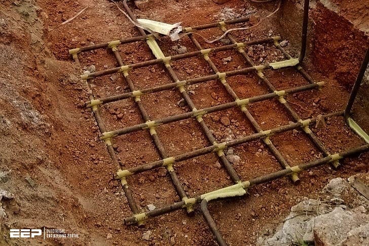
Plan of the grounding grid of the electrical substation (the

Best practice in power substation grounding
Substation Grounding Basics: Step, Touch, and Transferred Voltages

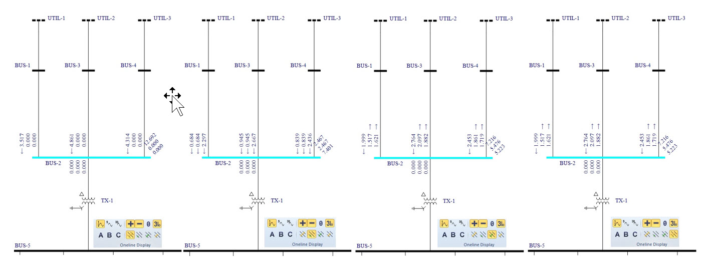
Case 3: Potential distribution (×10 kV) on ground surface obtained
Grounding Analysis – Ground Fault Current

Earthing grid design ➢ Estimated step Voltage
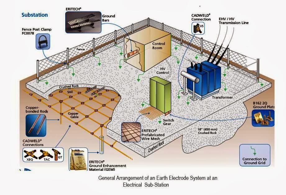
Substation Earthing System Design

Plan of the grounding grid of the electrical substation (the

Figure 4 from Computer aided design of the substation grounding

WAZIPOINT Engineering Science & Technology: Electrical Substation

How to Verify Ground Grid and Rod Installation ~ Electrical Knowhow

Figure 1 from Design and simulation of interconnected A.C

New substation powered up Oct. 14
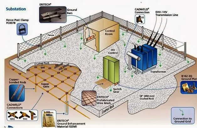
Substation Earthing System Design
Between the Poles: AU: Integrating 3D model-based structural and

Case 1: Potential distribution (×10 kV) on the ground surface